Showing posts with label Cisco. Show all posts

Friday, May 30, 2008

Configuring Cisco HWIC-3G

Some people asked me about configuring HWIC-3G-GSM or HWIC-3G-CDMA module. To read more information about these modules, you can open this link http://www.cisco.com/go/3g

Basically, Cisco 3G Wireless WAN HWIC provides a cost-effective alternative to ISDN dial back up and provides Business Continuity for critical applications.
  • Offers Broadband data rates up to 3.2 Mbps with EVDO and 3.6 Mbps with HSDPA
  • Supports CDMA and GSM/UMTS standards (EVDO Rev A / HSDPA)
  • Target Applications – WAN Backup, Rapid Deployment, Portable Applications
  • Supported on Cisco 1841 / 2800 / 3800 Series Routers
  • Embedded mini PCI express Cellular modem from Sierra Wireless
  • Modem firmware is upgradeable, it is not bundled with IOS
  • Multiple external antenna options for in-building deployments

Firmware

Sierra Wireless modem firmware is not bundled with IOS. Modem firmware upgrade may be required for bug fixes and enhancements

Search for new firmware here: http://www.cisco.com/kobayashi/sw-center/sw-wireless.shtml

IOS Commands to upgrade firmware:
microcode reload cellular cdma modem-provision
where pa-bay is 0 for HWIC, slot is the slot number where the 3G HWIC is plugged in (0-3).

Note: The firmware is packaged as a TAR archive. After copying to router flash, use the following command to untar:
archive tar /xtract flash: flash:


HWIC Insertion and Recognition


Router#show version

1 Virtual Private Network (VPN) Module

1 Cellular interface

DRAM configuration is 64 bits wide with parity enabled.
479K bytes of NVRAM.


Router#show diag
WIC Slot 0:
3G WWAN HWIC-HSDPA/UMTS/EDGE/GPRS-850/900/1800/1900/2100MHz
...
Product (FRU) Number : HWIC-3G-GSM
Version Identifier : NA

Router#show run
!
interface Cellular0/0/0
no ip address
shutdown
!


Profile Configuration CLI


Up to 16 Profiles can be configured at one time, when no profile is selected, profile 1 is used.

GSM Profile configuration command:
cellular x/x/x gsm profile create [chap|pap] username passwd
cellular x/x/x gsm profile delete


Profile Selection
Using “ATDT*98*#”in the dialer chat script

Router# cellular 0/0/0 gsm profile create 1 ISP.CINGULAR chap ISP@CINGULARGPRS.COM CINGULAR1

Profile 1 = INACTIVE*
--------
PDP Type = IPv4, Header Compression = OFF
Data Compression = OFF

Access Point Name (APN) = ISP.CINGULAR

Authentication = PAP

Username: ISP@CINGULARGPRS.COM, Password: CINGULAR1


New Cellular Interface configuration

The new Cellular interface is an Async Serial interface and requires following configuration

PPP Configuration
encapsulation ppp
ppp chap hostname
ppp chap password
ppp ipcp dns request


Dialer Configuration:
async mode interactive
dialer in-band

IP Address configuration
ip address negotiated

Sample Configuration:

interface Cellular0/0/0
ip address negotiated
ip nat outside
encapsulation ppp
dialer in-band
dialer string gsm
dialer-group 1
async mode interactive
ppp chap hostname dummy
ppp chap password 0 dummy
ppp ipcp dns request
!


Dialer/Chat Scripts


ATDT*98*#
where profile-number could be 1-16 and represents
the modem profile to be used for the call.

Example chat script:
chat-script gsm “” “ATDT*98*2#” TIMEOUT 30 CONNECT

For default Profile 1, profile number can be left out in the chat script:
chat-script gsm “” “ATDT*98#” TIMEOUT 30 CONNECT


Configuration Examples


Here we have the 3G as the primary connection, we use Dynamic IP Address and the Router acting as a DHCP server. The laptop connects to the router via wireless, in the router we have HWIC-AP module installed.

dot11 ssid test
authentication open
!
ip dhcp pool wlan-client
network 10.4.0.0 255.255.0.0
default-router 10.1.0.1
dns-server 66.102.163.231 66.102.163.232
!
chat-script gsm "" "ATDT*99#" TIMEOUT 60 "CONNECT"
!
interface Dot11Radio0/2/0
no ip address
!
ssid test
!
bridge-group 104
!
interface Cellular0/0/0
ip address negotiated
ip nat outside
encapsulation ppp
dialer in-band
dialer string gsm
dialer-group 1
async mode interactive
ppp chap hostname cisco@wwan.ccs
ppp chap password 0 cisco
ppp ipcp dns request
!
interface bv1
ip address 10.4.0.1 255.255.0.0
ip nat inside
!
ip route 0.0.0.0 0.0.0.0 Cellular0/0/0
!
ip nat inside source list 10 interface Cellular0/0/0 overload
!
access-list 1 permit any
dialer-list 1 protocol ip list 1
!
line 0/0/0
exec-timeout 0 0
script dialer gsm
login
modem InOut
no exec
!


Sunday, May 25, 2008

How to Configure an Access Server for Lab

If you see CBT Nuggets, TrainSignal, Cisco Video Mentor, the instructors can change access between devices easily. That's where an Access Server comes into play.
Moving around to plug/unplug a console cable from one to another is tired every time you want to configure/access different device. The solution to this problem is purchasing and configuring an Access Server.
Remote labs from Internetwork Expert also use an Access Server for the labs at racks.internetworkexpert.com.

If the Async port is serial like 2511's picture below, you will need a special octal cable CAB-OCTAL-ASYNC Cable. But if the Access Server Async ports are in RJ-45, you will only need a basic UTP RJ-45-to-RJ-45 rollover cable.


Once you've got your AS and the appropriate cable, you're ready to configure your AS. Below is the example diagram on how to connect the AS with the devices, and then you will connect one of the RJ-45 connectors to the console port of each one of your devices that has console port. If you're using an octal cable, make sure to note the number that's on the cable itself right below the connector, because that's very important.


In the above example, we have an Access Server, 2 routers, 1 switch, and 1 ASA.
Router 1 (R1) will be plugged using 1st cable and it will be using port 2001, 2nd cable will be port 2002, etc.

Basically we only need to configure a loopback interface, an an ip host name and port that point to the loopback address. The basic configuration will be like this:
hostname AS
!
!
ip host ASA 2004 1.1.1.1
ip host S1 2003 1.1.1.1
ip host R2 2002 1.1.1.1
ip host R1 2001 1.1.1.1
!
!
interface Loopback0
ip address 1.1.1.1 255.255.255.255
no ip directed-broadcast
!
There are two ways to connect to devices attached to an access server, you can terminate your exec session on the access server itself (one terminal window for all sessions), or you can terminate your exec session on the device connected to the access server (one terminal window for each session).

When you terminate your exec session on the access server you then “reverse telnet” to the individual devices connected to the access server. Normally to do this you first login to the access server and then issue the “show hosts” command to see the host mappings. Next, reverse telnet to them by typing the hostname and pressing enter. To get back to the access server issue the escape sequence CTRL-SHIFT-6-X. To do so hold ctrl and shift, hit 6, release all keys, then hit X. From the access server you can then open new connections or resume connections that you already have open.

When you terminate your exec session on the device connected to the access server, i.e. by telnetting to the access server at port 2001, you cannot issue the escape sequence to reconnect to the access server. In this situation you would open multiple terminal windows if you wanted to connect to multiple devices.

In my office lab, I made it similar to internetwork expert racks lab. Using login local, and have multiple user plus a menu.

For more information watch this class-on-demand video on using an Access Server.

Reference:

Wednesday, May 7, 2008

Extract a file or copy a folder from TFTP to flash

Sometimes you need to copy a bunch of files or a folder or maybe extract an archive file to a Cisco device. For instance, you need to upgrade the IOS of your Cisco Catalyst Switch or Cisco Aironet Access Points. If you need to upgrade to a newer IOS, usually Cisco provides an archived IOS.
For example, a 1200 Aironet IOS image will be available like this in cisco.com: c1200-k9w7-tar.123-8.JA2.tar.
That is a bit different compared to a Cisco Router image that used to be a *.bin file.

If you extract the
c1200-k9w7-tar.123-8.JA2.tar file, then you will have the image with a name like this: c1200-k9w7-mx.123-8.JA2, with another couple of files.
You will need to copy all these files into your Access Point.

So how to copy the the image to the Access Point?
Do we need to copy it one by one from tftp using "copy tftp flash" command?
The answer is no, that's where the "archive tar" command comes into play.

The example below, I extract a c1200-k9w7-tar.123-8.JA2.tar
file from my TFTP server (192.168.3.250) to Cisco Aironet 's flash:
ap#archive tar /xtract tftp://192.168.3.250/c1200-k9w7-tar.123-8.JA2.tar flash:
Loading c1200-k9w7-tar.123-8.JA2.tar from 192.168.3.250 (via BVI1): !
extracting info (274 bytes)
c1200-k9w7-mx.123-8.JA2/ (directory) 0 (bytes)
c1200-k9w7-mx.123-8.JA2/html/ (directory) 0 (bytes)
c1200-k9w7-mx.123-8.JA2/html/level/ (directory) 0 (bytes)
c1200-k9w7-mx.123-8.JA2/html/level/1/ (directory) 0 (bytes)
extracting c1200-k9w7-mx.123-8.JA2/html/level/1/appsui.js (557 bytes)
extracting c1200-k9w7-mx.123-8.JA2/html/level/1/back.shtml (498 bytes)!
...
...
...
(output truncated)
...
...
...

c1200-k9w7-mx.123-8.JA2/html/level/15/ap_contextmgr_scm_summary.shtml.gz (5559 bytes)!

extracting c1200-k9w7-mx.123-8.JA2/c1200-k9w7-mx.123-8.JA2 (3654874 bytes)!!!!!!!!!!!!!!!!!!!!!!!!!!!!!!!!!!!!!!!!!!!!!!!!!!!!!!!!!!!!!!!!!!!!!!!!!!!!!!!!!!!!!!!!!!!!!!!!!!!!!!!!!!!!!!!!!!!!!!!!!!!!!!!!!!!!!!!!!!!!!!!!!!!!!!!!!!!!!!!!!!!!!!!!!!!!!!!!!!!!!!!!!!!!!!!!!!!!!!!!!!!!!!!!!!!!!!!!!!!!!!!!!!!!!!!!!!!!!!!!!!!!!!!!!!!!!!!!!!!!!!!!!!!!!!!!!!!!!!!!!!!!!!!!!!!!!!!!!!!!!!!!!!!!!!!!!!!!!!!!!!!!!!!!!!!!!!!!!!!!!!!!!!!!!!!!!!!!!!!!!!!!!!!!!!!!!!!!!!!!!!!!!!!!!!!!!!!!!!!!!!!!!!!!!!!!!!!!!!!!!!!!!!!!!!!!!!!!!!!!!!!!!!!!!!!!!!!!!!!!!!!!!!!!!!!!!!!!!!!!!!!!!!!!!!!!!!!!!!!!!!!!!!!!!!!!!!!!!!!!!!!!!!!!!!!!!!!!!!!!!!!!!!!!!!!!!!!!!!!!!!!!!!!!!!!!!!!!!!!!!!!!!!!!!!!!!!!!!!!!!!!!!!!!!!!!!!!!!!!!!!!!!!!!!!!!!!!!!!!!!!!!!!!!!!!!!!!!!!!!!!!!!!!!!!!!!!!!!!!!!!!!!!!!!!!!!!!!!!!!!!!!!!!!!!!!!!
extracting c1200-k9w7-mx.123-8.JA2/5001.img (131328 bytes)!!!!!!!!!!!!!!!!!!!!!!!!!!
extracting c1200-k9w7-mx.123-8.JA2/5101.img (131328 bytes)!!!!!!!!!!!!!!!!!!!!!!!!!
extracting c1200-k9w7-mx.123-8.JA2/6301.img (131328 bytes)!!!!!!!!!!!!!!!!!!!!!!!!!!
extracting c1200-k9w7-mx.123-8.JA2/6701.img (131328 bytes)!!!!!!!!!!!!!!!!!!!!!!!!!!
extracting c1200-k9w7-mx.123-8.JA2/6701_cal.img (131328 bytes)!!!!!!!!!!!!!!!!!!!!!!!!!!
extracting c1200-k9w7-mx.123-8.JA2/info (274 bytes)
extracting info.ver (274 bytes)!
[OK - 5017600 bytes]
This is just a trick. To upgrade an IOS/image of a Cisco device, you can use the archive download-sw command or use the web GUI (for Cisco Aironet Access Point).

Sunday, March 9, 2008

Frame Relay Switching over a Tunnel

In 1996 Cisco Systems to Join with StrataCom, a leading supplier of Asynchronous Transfer Mode (ATM) and Frame Relay high-speed wide area network (WAN) switching equipment that integrates and transports a wide variety of information, including voice, data and video.
Cisco MGX Multiservice Switches provide Frame Relay services at the Provider Edge.
In a lab situation, we can configured Cisco IOS on standard routers and access servers to provide frame relay services.

There are several ways to relay frames in IOS:
  1. DCE-DCE (multiple DCE interfaces), basic switching using frame-route command
  2. DCE-DCE (multiple DCE interfaces, on newer IOS such as 12.2T), using connect command
  3. Hybrid, 1 DCE and 1 DTE
  4. Back-to-Back, which requires lmi to be disabled with no keepalive
  5. Tunnel Methods
To learn how to configure Cisco router as a Frame Relay switch, you can read my friend's blog, awa here.

Here I will give some configuration examples of Frame Relay switch using Tunnel methods.
Suppose you need 4 ports Frame Relay Switch for making a Full Mesh Frame Relay topology, but all you had is only 2 Cisco routers with 2 serials and 1 ethernet interfaces.
IOS permits us to send a switched frame relay packets over an IP tunnel. This permits the frame relay encapsulated serial interfaces to be located on different routers.
This diagram below may be looked complex, but its only just a Full Mesh Frame Relay topology.


There are 2 fundamental tricks use to get this trick to work:
  1. Using tunnel interface as the destination in the frame-route statements
  2. Making the same PVC is referenced by the same DLCI on both side of the tunnels
Configuration of SW1:
interface serial 0
no ip address
encapsulation frame-relay
no fair-queue
clock rate 128000000
frame-relay intf-type dce
frame-route 102 interface Tunnel0 122
frame-route 103 interface Tunnel0 123
frame-route 104 interface Serial3 401

interface tunnel 0
ip unnumbered ethernet 0
tunnel source ethernet 0
tunnel destination 172.16.10.5
Configuration of SW2:
interface serial 1/0
no ip address
encapsulation frame-relay
clock rate 128000000
frame-relay intf-type dce
frame-route 201 interface Tunnel0 122
frame-route 203 interface Serial1/1 302
frame-route 204 interface Tunnel0 422

interface tunnel 0
ip unnumbered FastEthernet 0/0
tunnel source FastEthernet 0/0
tunnel destination 172.16.10.7

Frame Relay Basics

Frame Relay is an OSI Layer 2 Wide Area Network Protocol. It is commonly implemented as a WAN access protocol on the link between the customer and the provider edge. It also can be implemented as core protocol.
Frame Relay permits multiple Permanent Virtual Circuits (PVC) to use the same physical link, providing a kind of Layer 2 VPN between customer locations. These PVCs can be flexibly designed as Full Mesh or Hub and Spoke depending on traffic patterns and budgets.

Frames are relayed using the Data Link Connection Identifier (DLCI). The DLCI uniquely identifies traffic for a given PVC on a given physical channel, it is a 10 bit number that can vary between 0 and 1023. I will use the diagram below to explain the usage of DLCI.

If HQ want to send packets destinate to Branch A, HQ's router need to know which DLCI to use for packet with next hop of 123.3. This mapping of far side Layer 3 address to near side Layer 2 address can be created statically or dynamically using inverse arp.
In mapping table the router determine the traffic with the next hop of 123.2 should go out on the PVC designated by DLCI 102. It encapsulates the packet in the frame and search the DLCI of 102 address in the frame header, and send it out the interface to Switch1. The Switch1 replaces the DLCI of 102 in the frame header with DLCI 112 and sends it on Switch2. Switch2 rewrites the header with DLCI 201 and sends the frame on to the Branch A router. The same process takes places from packets from HQ destinated to Branch B.

In the diagram, you see the Headquarters and Branches connected over Frame Relay. The Frame Relay Service Provider cloud consists of 2 SW1 and SW2 which are Cisco Routers that configured for Frame Relay Switching. Notice that the customer router connected to Frame Relay cloud and shared the same subnet 172.16.123.x.

Frame Relay interfaces in Cisco can be configured as:
  • DTE (Data Terminal Equipment), Serial interfaces at R1, R2, and R3 as routed interfaces
  • DCE (Data Communications Equipment), Serial 1/0 at Switch 1, Serial 0 and Serial 2 at Switch S2
  • NNI (Network-to-Network Interface), Serial 0/0 at Switch 1, Serial 1 at Switch S2

Configuration of DTE interfaces in R1:
interface serial 1/0
ip address 172.16.123.1 255.255.255.0
clock rate 128000
no dce-terminal-timing-enable
Configuration of DCE interfaces in SW1:
interface serial 1/0
no ip address
encapsulation frame-relay
frame-relay intf-type dce
frame-relay route 102 interface serial 0/0 112
frame-relay route 103 interface serial 0/0 113
Configuration of NNI interfaces in SW1:
interface serial 0/0
no ip address
encapsulation frame-relay
no fair-queue
frame-relay intf-type nni
frame-relay route 112 interface serial 0/0 102
frame-relay route 113 interface serial 0/0 103

Sunday, February 3, 2008

Cisco Router Simulator with Dynamips / Dynagen

I will explain how to emulate our PC in order to emulate Cisco Router hardware and run virtual IOS processes on our local desktop.

What is Dynamips?
Dynamips is an IOS virtualization program that is similar to half VMware on desktop in order to simulate different hardware platforms.
Dynamips is different than traditional simulator e.g. Boson, Packet Tracer, Router eSim.
Dynamips doesn't emulate the IOS, it emulates the router hardware on PC, boot IOS images into different logical router processes, and they're gonna be able to talk with each other with whatever protocols in that particular IOS images.

In order to run dynamips:
-Windows / Mac Os / Linux
-Dynamips "hypervisor" that used to emulate router hardware
-Dynagen that is used to create configuration file and booting the hypervisor processes
-Dynamips included in Dynagen installer packare
-Actual IOS images
-Any Terminal emulation software like HyperTerminal, SecureCRT, Tera Term, etc

Windows (click here for Video Tutorial)
1. install winpcap, in order to support the network interfaces card to talk to the dynamips processes
2. install dynagen that includes the dynamips hypervisor
3. start Dynamips Server
4. run the *.net file config lab

Linux (click here for Video Tutorial)
1. Download dynagen using wget and extract using tar zxvf it to /opt/dynamips directory
2. Change directory to dynagen, check the README.txt to see which version of dynamips is required then go to dynamips blog to download the required version of dynamips.
3. Download the required version of dynamips using wget also into /opt/dynamips directory
4. Use 'chmod 755' command to make the dynamips binary executable
5. Navigate to /usr/bin directory to create symbolic links for the dynamips and dynagen program
6. Create a symbolic link to dynamips program give it a name e.g. dynamips. This will allow you to just type dynamips from anywhere to run the program. Here is the example:
ln -s /opt/dynamips/dynamips-0.2.7.-RC2-x86.bin dynamips
7. Create a symbolic link to dynagen program give it a name e.g. dynagen. This will allow you to just type dynagen from anywhere to run the program. Here is the example:
ln -s /opt/dynamips/dynagen-0.9.1/dynagen dynagen
8. Create a directory for IOS images and move IOS image to this directory.
mkdir /opt/dynamips/images
Configure *.net dynagen lab file that is gonna be used to configure what individual router instances we gonna run, what interfaces they have and what IOS image that they are gonna be running.
In sample_lab there are templates that can be changed. For example we want to try the simple1 lab inside simple1 directory with the name of configuration file is simple1.net. Change the bold text (c7200-adventerprisek9-mz.124-4.T1.bin) below becomes your IOS image file name.

Windows:
# Simple lab

[localhost]

[[7200]]
image = \Program Files\Dynamips\images\c7200-adventerprisek9-mz.124-4.T1.bin
# On Linux / Unix use forward slashes:
# image = /opt/7200-images/
c7200-adventerprisek9-mz.124-4.T1.bin
npe = npe-400
ram = 160

[[ROUTER R1]]
s1/0 = R2 s1/0

[[router R2]]
# No need to specify an adapter here, it is taken care of
# by the interface specification under Router R1


Linux:
# Simple lab

[localhost]

[[7200]]
# image = \Program Files\Dynamips\images\c7200-adventerprisek9-mz.124-4.T1.bin
# On Linux / Unix use forward slashes:
image = /opt/7200-images/
c7200-adventerprisek9-mz.124-4.T1.bin
npe = npe-400
ram = 256

[[ROUTER R1]]
s1/0 = R2 s1/0

[[router R2]]
# No need to specify an adapter here, it is taken care of
# by the interface specification under Router R1


Start Dynamips Server (launch the Hypervisor process).
Windows: Double click the 'Dynamips Server shortcut' usually on desktop

Linux
: dynamips -H 7200 &
Note: The '&' character instructs the process in the background.


Once we have start the Dynamips Server, then we initiate the configured *.net config file lab. In this example I try to run simple.net lab. Then a new window will popped up.

Windows
: Double click the 'simple1.net' file usually in C:\Program Files\Dynamips\sample_labs\simple1

Linux
: dynagen simple1.net


List the available devices in the lab using list command.

Windows: Connect to a router using telnet [device name] command e.g. telnet R1
Linux: Connect to router using telnet client such as putty on port 2000

A new window for the router will came up.


Windows: You will see some error messages like below
% Crashinfo may not be recovered at bootflash crashinfo % This file system device reports an error
Linux: You might not have this error messages.

Windows: To fix this error we need to format the bootflash using command: format bootflash:
After finish formatting the bootflash, we need to make an adjustment to the idle-pc parameter in order to drop the CPU utilization on PC.

Now close the R1 telnet window and go back to console with a window title "Dynagen"


To get idle-pc value use command:
idlepc get [router name]
e.g. idlepc get R1
Choose the value marked with "*". If there is no "*" mark in first attempt, just try again the command idlepc get R1.

After applied the idlepc value, don't forget to save the idlepc value using command:
idlepc save [router name] db


You will notice the drop in CPU utilization since the idle-pc value already changed.

OK! Now we have a virtual Wide Area Network with Cisco Routers!

Additional information and materials:

Thursday, January 31, 2008

Cisco Nexus 7000 Series Switch Family

SAN JOSE, Calif., Jan. 28, 2008 - Cisco® announced today an innovative family of data center-class switching platforms, the Cisco Nexus Series, to meet customer demands for next-generation mission-critical data centers. As the data center transitions to a more services-centric model, the network plays a pivotal role in orchestrating virtual IT resources and scaling workloads. The Cisco Nexus 7000 Series was designed with this environment in mind, delivering the infrastructure chapter of Cisco's Data Center 3.0 vision.

Today's announcement features a new data center platform with both hardware and software innovations, including:

  • The Cisco Nexus 7000 Series, the flagship data center-class switching platform combining Ethernet, IP, and storage capabilities across one unified network fabric
  • The Cisco Trusted Security (TrustSec) architecture
  • An advanced operating system, the Cisco Nexus Operating System (Cisco NX-OS), and the Cisco Data Center Network Manager

Introducing the Nexus 7000 Series: Purpose Built for Data Centers

The Cisco Nexus 7000 Series is the flagship member of the Cisco Nexus Family, the first in a new data center class of switching products. The Nexus 7000 is a highly scalable modular platform that delivers up to 15 terabits per second of switching capacity in a single chassis, supporting up to 512 10-gigabits-per-second (Gbps) Ethernet and future delivery of 40- and 100-Gbps Ethernet. Its unified fabric architecture combines Ethernet and storage capabilities into a single platform, designed to provide all servers with access to all network and storage resources. This enables data center consolidation and virtualization. Key components of the unified fabric architecture include unified I/O interfaces and Fibre Channel over Ethernet support to be delivered in the future.

The Nexus 7000 is designed specifically for the data center with improved airflow, integrated cable management, and a resilient platform architecture. The data plane is fully distributed and, when coupled with the Cisco NX-OS operating system, is designed to enable zero service-disruption upgrades on production systems. This provides a seamless systems design that reduces administrative tasks and simplifies complex systems operations.

More information:

Cisco Telco Summit 2008


For years Cisco has becomes a Network Solution. Now Cisco start to enter telecommunication market with introducing Next-Generation Network solutions.

To introduce the telecommunication solutions, Cisco convokes Cisco Telco Summit 2008 at Shangri-La Hotel Jakarta, on the 5th February 2008. This summit is meant to exhibit various Cisco's innovation and solutions that will lead telecommunication companies toward the future, where telecommunication will be more personal, fast, and flexible.
More information:

Sunday, January 20, 2008

Configuring Cisco Catalyst Switch

Here I will explain about configuring a Cisco Catalyst Switch
  • Preparation to Configure a Switch
  • Basic Switch Configuration:
    • Management Interface Considerations
    • Configure Management Interface
    • Configure Default Gateway
    • Verify Configuration
    • Configure Duplex and Speed
    • Configure a Web Interface
Prepare to Configure the Switch
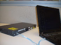
The initial startup of a Catalyst switch requires the completion of the following steps:
Step 1. Before starting the switch, verify the following:
All network cable connections are secure.
Your PC or terminal is connected to the console port. Your terminal emulator application, such as HyperTerminal is running and configured properly. The figure shows a PC connected to a switch using the console port.
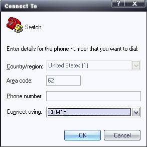
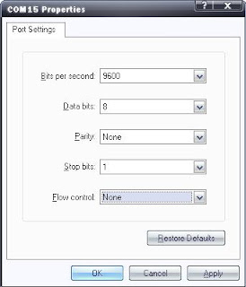
The figure below shows the correct configuration of HyperTerminal, which can be used to view the console of a Cisco device. In here I'm using a USB-to-RS232 converter the driver make a new Serial Port COM 15. If your PC or Laptop already has a Serial Port it should be COM 1.


Step 2
. Attach the power cable plug to the switch power supply socket. The switch will start. Some Catalyst switches, including the Cisco Catalyst 2960 series, do not have power buttons.
Step 3. Observe the boot sequence as follows:
When the switch is on, the POST begins. During POST, the LEDs blink while a series of tests determine that the switch is functioning properly. When the POST has completed, the SYST LED rapidly blinks green. If the switch fails POST, the SYST LED turns amber. When a switch fails the POST test, it is necessary to repair the switch.
Observe the Cisco IOS software output text on the console.

The Boot Process on console should be like this:

Copyright (c) 1986-2006 by Cisco Systems, Inc,.

Compiled Fri 28-Jul-06 04:33 by yenanh

Image text-base: 0x0o003000, data—base: OxOOAA2F34

flashfs[l]: 602 files, 19 directories

flashfs[1]: 0 orphaned files, 0 orphaned directories flashfs[1r]: Tota1 bytes: 32514048

flashfs[1]: Bytes used: 7715328

flashfs[1]: Bytes available: 24798720

flashfs[1]: flashfs fsck took 1 seconds.

flashfs[1]: Initia1ization complete....done Initia1izing flashfs.

POST: CPU MIC register Tests : Begin

POST: CPU MIC register Tests : End, status Passed

POST: PortASIC Memory Tests : Begin

POST: PortASIC Memory Tests : End, Status Passed

POST: CPU MIC PostASIC interface Loopback Tests : Begin

POST: CPU MIC PostASIC interface Loopback Tests : End, Status Passed

POST: PostASIC RingLoopback Tests : Begin

POST: PostASIC RingLoopback Tests : End, Status Passed

POST: PostASIC CAM Subsystem Tests: Begin

During the initial startup of the switch, if POST failures are detected, they are reported to the console and the switch does not start. If POST completes successfully, and the switch has not been configured before, you are prompted to configure the switch.


Management Interface Considerations
An access layer switch is much like a PC in that you need to configure an IP address, a subnet mask, and a default gateway. To manage a switch remotely using TCP/IP, you need to assign the switch an IP address. In the figure, you want to manage S1 from PC1, a computer used for managing the network. To do this, you need to assign switch S1 an IP address. This IP address is assigned to a virtual interface called a virtual LAN (VLAN), and then it is necessary to ensure the VLAN is assigned to a specific port or ports on the switch.

The default configuration on the switch is to have the management of the switch controlled through VLAN 1. However, a best practice for basic switch configuration is to change the management VLAN to a VLAN other than VLAN 1. The implications and reasoning behind this action are explained in the next chapter. The figure illustrates the use of VLAN 99 as the management VLAN; however, it is important to consider that an interface other than VLAN 99 can be considered for the management interface.


Configure Management Interface
To configure an IP address and subnet mask on the management VLAN of the switch, you must be in VLAN interface configuration mode. Use the command interface vlan 99 and enter the ip address configuration command. You must use the no shutdown interface configuration command to make this Layer 3 interface operational. When you see "interface VLAN x", that refers to the Layer 3 interface associated with VLAN x. Only the management VLAN has an interface VLAN associated with it.

Note that a Layer 2 switch, such as the Cisco Catalyst 2960, only permits a single VLAN interface to be active at a time. This means that the Layer 3 interface, interface VLAN 99, is active, but the Layer 3 interface, interface VLAN 1, is not active.

Here is the Cisco IOS CLI Command Syntax:
S1#configure terminal
S1(config)#interface vlan 99
S1(config-if)#ip address 172.17.99.11 255.255.0.0
S1(config-if)#no shutdown
S1(config-if)#end
S1#configure terminal
S1(config)#interface fastethernet 0/18
S1(config-if)#switchport mode access
S1(config-if)#switchport acces vlan 99
S1(config-if)#end
S1#copy running-config startup-config


Configure Default Gateway

You need to configure the switch so that it can forward IP packets to distant networks. The default gateway is the mechanism for doing this. The switch forwards IP packets with destination IP addresses outside the local network to the default gateway. In the figure, router R1 is the next-hop router. Its IP address is 172.17.99.1.

To configure a default gateway for the switch, use the ip default-gateway command. Enter the IP address of the next-hop router interface that is directly connected to the switch where a default gateway is being configured. Make sure you save the configuration running on a switch or router. Use the copy running-config startup-config command to back up your configuration.


Verify Configuration
Here is an abbreviated screen output showing that VLAN 99 has been configured with an IP address and subnet mask, and Fast Ethernet port F0/18 has been assigned the VLAN 99 management interface:
S1#show running-config
...
!
interface FastEthernet0/18
switchport access vlan 99
switchport mode access
...
!
interface Vlan99
ip address 172.17.99.11 255.255.255.0
no-ip route cache
!
Show the IP Interfaces
Use the show ip interface brief to verify port operation and status. Y

The mdix auto Command

You used to be required to use certain cable types (cross-over, straight-through) when connecting between specific devices, switch-to-switch or switch-to-router. Instead, you can now use the mdix auto interface configuration command in the CLI to enable the automatic medium-dependent interface crossover (auto-MDIX) feature.

When the auto-MDIX feature is enabled, the switch detects the required cable type for copper Ethernet connections and configures the interfaces accordingly. Therefore, you can use either a crossover or a straight-through cable for connections to a copper 10/100/1000 port on the switch, regardless of the type of device on the other end of the connection.

The auto-MDIX feature is enabled by default on switches running Cisco IOS Release 12.2(18)SE or later. For releases between Cisco IOS Release 12.1(14)EA1 and 12.2(18)SE, the auto-MDIX feature is disabled by default.


Configure Duplex and Speed
You can use the duplex interface configuration command to specify the duplex mode of operation for switch ports. You can manually set the duplex mode and speed of switch ports to avoid inter-vendor issues with autonegotiation. Although there can be issues when you configure switch port duplex settings to auto, in this example, S1 and S2 switches have the same duplex settings and speeds. The figure describes the steps to configure the port F0/1 on the S1 switch.

Here is the Cisco IOS CLI Command Syntax:
S1#configure terminal
S1(config)#Interface fastethernet 0/1
S1(config-if)#duplex auto
S1(config-if)#speed auto
S1(config-if)#end
S1#copy running-config startup-config

Configure a Web Interface
Modern Cisco switches have a number of web-based configuration tools that require that the switch is configured as an HTTP server. These applications include the Cisco web browser user interface, Cisco Router and Security Device Manager (SDM), and IP Phone and Cisco IOS Telephony Service applications.

To control who can access the HTTP services on the switch, you can optionally configure authentication. Authentication methods can be complex. You may have so many people using the HTTP services that you require a separate server specifically to handle user authentication. AAA and TACACS authentication modes are examples that use this type of remote authentication method. AAA and TACACS are authentication protocols that can be used in networks to validate user credentials. You may need to have a less complex authentication method. The enable method requires users to use the server's enable password. The local authentication method requires the user to use the login username, password, and privilege level access combination specified in the local system configuration (by the username global configuration command).

Here is the Cisco IOS CLI Command Syntax:
S1#configure terminal
S1(config)#ip http authentication enable
S1(config)#ip http server
S1(config)#end
More information on TACACS.
More information on AAA.

References:

Wednesday, November 14, 2007

CCNP and CCIP

After getting CCNA certification, you usually will get confused in choosing between CCNP and CCIP. CCVP and CCSP usually pursued after getting CCNP, because CCNP is like the fundamentals for professionals. Both CCNP and CCIP requires 4 exams.

CCNP
642-901 BSCI Building Scalable Cisco Internetworks (BSCI)
642-812 BCMSN Building Cisco Multilayer Switched Networks (BCMSN)
642-825 ISCW Implementing Secure Converged Wide Area Networks (ISCW)
642-845 ONT Optimizing Converged Cisco Networks (ONT)

CCIP
642-901 BSCI
OR
642-892 Composite
Building Scalable Cisco Internetworks (BSCI)
642-642 QOS Implementing Cisco Quality of Service (QoS)
642-661 BGP Configuring BGP on Cisco Routers (BGP)
642-611 MPLS Implementing Cisco MPLS (MPLS)

CCNP, do this if you want to work for a mid size company. Maybe you like to deal with firewalls too or with operating systems. Pure CCNP employees needs to have other skills because their company need a good networking expertise also other skills. Requires:
* A CCNA standing
* Building Cisco Scalable Internetworks
* Building Cisco Multilayer Switched Networks
* Building Cisco Remote Access Networks
* Cisco Internetwork Troubleshooting

CCIP, do this if you want to be a network specialist. Not a lot of companies would need to have MPLS skilled people, except ISP.
Requires:
* A CCNA standing
* Building Cisco Scalable Internetworks
* Implementing Cisco Quality of Service
* Implementing Cisco MPLS
* Configuring BGP on Cisco Routers

CCNP is like a foundation, it is better to learn about routing and switching first before you learn about complicated topics like MPLS. Simply because there is a bit of switching and routing involved in CCIP

It depends on what you are seeking in your future career and your current job. CCNP is for corporate sector, focuses on LAN tan WAN, meanwhile CCIP is ISP sector and just focuses on more WAN than LAN networks.

CCNP track to the Routing & Switching CCIE also covering enterprise-related technologies. CCIP, on the other hand, is viewed with a focus on "Service Provider" technologies. It tracks to the Service Provider CCIE.

In the grand scheme of things, depending on what specific areas you want to get in to, it likely doesn’t make any difference which one you pursue. Both will push you to a better understanding of the inner workings of the routers and switches on a network. If you want to take both, its better to get CCNP first. Materials in CCIP is like advanced materials from CCNP, BGP which is part of BSCI, QOS reviewed in ISCW, MPLS which has fundamental concepts in BCMSN. But at the end of the day, it's your decision. Scott Morris said, "There’s very little in the technology arena that is a “waste” of your time and energy. So take whichever path you believe will deliver you to the career or job that you want. But either way won’t be a waste."

References:

Saturday, August 18, 2007

Cisco Certification (CCNA)

Many of my friends asked me about Cisco Certifications. Bay, do you take the Cisco Certification? How can I get it? When should I take it? They ask questions like that and usually they think there's only 1 Cisco Certification which is not true. For further explanation, we can directly navigate the Cisco Systems, Inc website. But people prefer to ask directly to someone who knows about it or read articles about the certification in general. I'd like to explain a bit about the Cisco Carrer Certifications & Path especially CCNA. So, for masters/seniors who read this posting please correct me if I got it wrong. I'm still a college students, sorry if make mistake in my explanation, thanks.

Cisco Systems offer three levels of certification:
  1. Associate
  2. Professional
  3. Expert
The Associate level includes the new CCENT certification. The Expert level includes the CCIE certification, which represents the highest level of achievement.

It has six different paths:
  1. Routing & Switching
  2. Design
  3. Network Security
  4. Service Provider
  5. Storage Networking
  6. Voice
So that we can match our certification path to our job role or industry.

While in focused areas, network professionals can enhance their core networking knowledge by achieving specialist certification in technologies such as security, IP telephony, and wireless.

The first step in general Cisco Career Certifications begins either with CCENT as an interim step to Associate level, or directly with CCNA for network operations or CCDA for network design.

Why become a CCNA?

The CCNA program was created to provide a solid introduction not only to the Cisco Internetwork Operating System (IOS) and Cisco hardware, but also to internetworking in general. Ok, I will try to explain the first level only which is Associate. The CCNA certification was the first in the new line of Cisco certifications, and was the precursor to all current Cisco certifications.

How do you become a CCNA?
There are 2 ways:
  1. Pass either 640-801 CCNA exam or 640-802 CCNA exam.
  2. Pass both 640-821 INTRO & 640-811 ICND or 640-822 ICND1 & 640-816 ICND2
640-802 CCNA, 640-822 ICND1 and 640-822 ICND1 exams are new curricula. According to some news from Cisco website, after November 6 2007, there will be no 640-801 CCNA, 640-821 INTRO and 640-811 ICND exams.
New Exam questions have been updated to validate the skills necessary to implement today’s small to medium-sized branch networks, and include new topics, such as network address translation and IPv6, basic security controls, and basic WLAN concepts. A full list of exam topics is provided at www.cisco.com/go/ccna. The new exams also feature more performance-based questions, to better assess candidate competency.

Cisco has created another certification track for network designers in Associate level. The two certifications within this track are the CCDA (Cisco Certified Design Associate). To achieve this, we must pass the Design exam (640-861). To pass this test, you must
understand how to do the following:
  • Design simple routed LAN, routed WAN, and switched LAN and ATM LANE networks.
  • Use Network-layer addressing.
  • Filter with access lists.
  • Use and propagate VLAN.
  • Size networks.
The Cisco CCENT (Cisco Certified Entry Networking Technician) will certify the practical skills required for entry-level network support positions. The new certification validates the ability to install, operate, and troubleshoot a small branch network, including configuring a router and switch, connecting to a WAN, and implementing basic network security. It is a tangible, but optional, first step in earning the CCNA certification, the foundation-level certification for networking careers. Recipients of the new certification also gain access to the Cisco Certification community, which enables them to access additional training resources and use the new CCENT logo to indicate their achievement.
To achieve the entry-level CCENT certification we must pass the ICND1 640-822 exam. Taking the INTRO 640-821 exam will not qualify us for the CCENT certification.

CCNA certifications are valid for three years. To recertify, either pass the current CCNA exam, or pass the ICND2 exam, or pass any 642 professional level.

To pass the exam, we should have trainings or study from book like Study Guide books published by Sybex or Cisco Press. There are 3 ways to be prepared for CCNA
  1. Exam Preparation 640-801 CCNA or 640-802 CCNA
  2. Exam Preparation 640-821 INTRO & 640-811 ICND or 640-822 ICND1 & 640-816 ICND2
  3. CNAP-CCNA (Cisco Networking Academy Program), this is a CCNA Courses 1 through 4 of the Academy program, equivalent to 280 hours of instruction, provide students with a basic foundation in networking. Students who successfully complete this portion of the program are eligible to earn Cisco Certified Network Associate (CCNA™) certification. The first four courses are available at the secondary and post-secondary levels. This Networking Academy covers the knowledge in networking starting from Networking Basics, Routers & Routing Basics, Switching Basics & Intermediate Routing until WAN Technologies. Cisco recommends taking the CCNA exam after completing these courses of the CCNA curriculum.
References: